Project - BSA LPI |
The solution of the task of searching for pulsars and transients became possible thanks to the modernization of the BSA LPI radio telescope, carried out in 2010-2012.
BSA LPI telescope is located in Pushchino, Moscow region, on the territory of the Pushchino Radio Astronomy Observatory.
PRAO ASC LPI
BSA is located in Pushchino of Moscow region at PRAO ASC LPI.
PRAO ASC LPI is Pushchino Radio Astronomy Observatory of Astro Space Center of Lebedev Physical Institute of Russian Academy of Sciences. After renaming of all the institutes to «federal institutions» the name of our institute became more complex, but we present here the old name which we are used to.
BSA stands for Big Scanning Array. This is the largest array in meter-range of wave lengths.
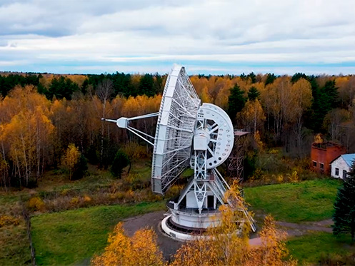
Besides BSA Pushchino Observatory has 2 more operating antennas: DCR-1000 – Dipole Cross-shaped Radio telescope, and RT-22 – a radio telescope with a diameter of 22 m.
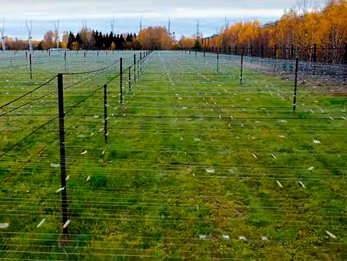
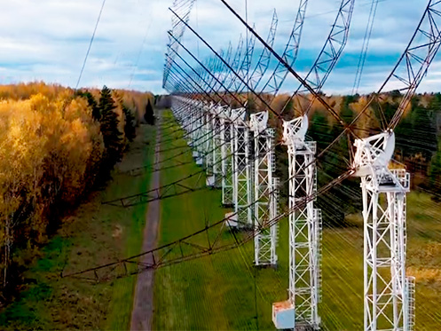
Radio telescopes of the Pushchino Observatory - view from a quadrocopter
(film of Wind of Eternity) |
||
Pushchino Radio Astronomy Observatory |
BSA LPI Radio Telescope |
|
 |
 |
|
Wide-Band Cross-type Radio Telescope DKR-1000 |
RT-22 LPI Radio Telescope |
|
 |
 |
|
BSA LPI
BSA LPI was built in 1974. It consists of 16,384 half-wave dipoles and occupies an area of more than 7 hectares. Initially the central receiving frequency of the array was 102.5 MHz and the effective area was 20 000 - 25 000 m2. After the government sold this range to business entities the array was modernized. The central receiving frequency became 110.25 MHz, with the effective area decreasing down to 10,000 – 15,000 m2.
In 2009 a grant was received for conducting works according to the «Space weather» program. This grand helped to modernize the array significantly. The main period of optimization was in 2010 – 2012. New amplifiers with 1 input and 4 independent outputs were set, digital receivers were created, Batler matrices were replaced. Actually, 4 independent radio telescopes can operate on the base of BSA LPI.
The first radio telescope – is an old variant of the array (BSA-1).
In this variant the array has 512 beams formally covering declinations from about -28о to +88о
and a digital pulsar receiver which can be connected to any of these beams.
In practice they try to use declinations from -5о to about +75о.
Below -5о interferences are high and the effective area is small, above +75о
source observation takes much time.
The second radio telescope is a multi-beam array operating for monitoring programs (BSA-2).
The third radio telescope is an old variant of the array on a new base. As it’s put into operation the first radio telescope will be closed. Prior observations show that the effective area of BSA-3 will increase by a factor of 3 – 4 compared to the operating variant BSA-1. Using the digital receiver observations can be conducted at few beams in a raw.
The fourth radio telescope is a test system for performance audio of separate parts of the array.
Array modernization in more details
BSA-2 has 128 non-exchangeable beams. These beams cover declinations from -8o to +55o. However, at the current moment there is a multi-channel digital receiver enabling registration of the signal from 96 beams of the array covering declinations from -8o to +42o.
The coverage of beams is made to be at 0.4 of the power level.
ЭThe effective area of BSA-2 normalized to the zenith equals to 47,000 ± 2,500 m2.
The full bandwidth of receiving frequencies is 2.5 MHz.
Because BSA beams are fixed and the array field is stationary the array sensibility differs significantly in different directions.
Fig. 1 shows a change in the sensibility depending on the direction in the sky.

For calibration the power of signals arriving at the input of low-noise amplifiers (LNA) a signal given from a special (noise) generator.
This signal enables measure of the main parameters of the radio telescope:
- The noise temperature of the system;
- The effective area of the array;
- Performance audit of the system of distributed amplification and its separate elements.
The LNA input switches between the array and the calibration noise generator.
The noise generator forms two levels of the calibrated signal referencing to the noise temperature
of the optimal load and the noise temperature of the turned-on generator.
The noise temperature of the optimal load equals atmospheric temperature.
The noise temperature of the signal of the calibration generator equals to 2400 K and depends weakly
on atmosphere temperature. Measured changes in step-like data don’t exceed ±3% if atmosphere
temperature changes from -15оC to +43оC.
Fig. 2 demonstrates the map of all observed area in the sky during one day.

Multi-channel digital radiometer consists of two registrars – industrial computers with a multi-channel receiving and recording module. They enable registration of a signal for 96 beams of the radio telescope. Every registrar consists of six 8-channel modules for digital signal processing. At the module input 4 paired ADC TI ADS62P29 are installed.
Digital processing is conducted with field programmable logic device – FPLD EP3SL780C3 (Stratix III, Altera).
In use are:
- The method of direct signal digitizing;
- Digital filtration system;
- Frequency translation;
- Spectral analysis.
The digitizing frequency is 230 MHz,
the band of the registered signal in every channel equal to 2.5 MHz,
the central frequency is 110.25 MHz.
Resources of FPLD help to realize at one microcircuit:
- 8 independent video converters;
- Filtration of high- and low-frequency signals;
- Spectral analysis and process of 8 independent data flows.
In the registrar module possibility of record to a hard disc is realized for:
- The signal power in 32 spectral channels with a frequency resolution of 78 kHz;
- The signal power in 6 spectral channels with a frequency resolution of 415 kHz;
The temporal resolution of the signal equals to 12.5 ms or 100 ms.
Control of the times service is made in the beginning of every hour of observations. The first point is digitized with an accuracy of not worse than 5 ms. The accuracy of channel test during an hour is defined by the frequency of quartz frequency generatrix of a digital receiver. The estimated maximum possible recedence time at an-hour interval is:
±25 ms (± 2 points of primary "long data") и
±100 ms (± 1 point of primary "short data").
From July 2014 simultaneous data record has been conducted with a time constant of 100 ms in 6 frequency channels ("short data"), and with a time constant of 12.5 ms in 32 frequency channels ("long data").
As for 2017 the total size of cumulative data exceeds 110 TB.
Papers
- Tyul'bashev S.A., Tyul'bashev V.S., Oreshko V.V., Logvinenko S.V.
Detection of new pulsars at 111 MHz
Astronomy Reports, 2016, 60, 220-232
- Shishov V.I., Chashei I.V., Oreshko V.V., Logvinenko S.V., Tyul'bashev S.A., Subaev I.A., Svidskii P.M., Lapshin V.B., Dagkesamanskii R.D.
Monitoring of the turbulent solar wind with the upgraded Large Phased Array of the Lebedev Institute of Physics: First results
Astronomy Reports, 2016, 60, 1067-1082